Improving Gas Holes of Die-cast Filter Parts by CAE
The development trend of lightweight and functional integration of aluminum alloy die castings has led to the diversification and complexity of the structure of the parts, and there are many parts with poor die casting processability and uneven wall thickness. For such parts with great wall thicknesses difference and very complex structures, eddies and entrainment will inevitably be generated due to the molten metal hitting the complex wall in the die-cast process. If the design of the runner system and the overflow system is unreasonable, it will cause the gas dissolved in the aluminum liquid to be difficult to completely discharge from the cavity, which will inevitably lead to gas holes in the interior and surface of the die casting. At the same time, the molten aluminum cannot be effectively compensated in the rapid solidification process due to the complex structure of the parts, resulting in shrinkage porosity in the casting. Parts with gas holes or shrinkage porosity on the surface and inside cannot meet their technical requirements, causing the parts to be scrapped, which brings great waste to the enterprise.
Take a filter for communication components as an example. Use CAE to simulate the original plan and analyze the root cause of the defect; propose an optimized plan to effectively solve the problem of gas holes of the product.
Figure 1 is a structural picture of a certain filter for a communication component. The weight of the casting is 3 kg, and the material is DC01. The size of the casting is 414×333×38 mm. The maximum wall thickness is 4 mm. The minimum wall thickness is 2 mm, and the average wall thickness is 3 mm. The inner cavity is staggered with ribs similar to the labyrinth structure, which is a relatively complex casting. This part is a filter used in mobile communication transmitter base stations with high technology so far. Compared with the traditional filter, its internal cavity structure is more complicated, and there are many and complicated labyrinth structures. The wall thickness is uneven, and there are many columns and mounting holes. The complicated structure will inevitably lead to insufficient filling of the molten aluminum and the occurrence of partial wrapping gas in the casting. In addition, the requirement for internal compactness of the casting is high, and the product needs to be electroplated. When the casting is electroplated and baked, the gas in the hole is heated and expands, which will cause bubbles on the surface of the casting. Therefore, appropriate methods must be used to solve the gas hole in the production. How to reduce the gas in the casting is a difficulty in the design of the entire die-cast process.
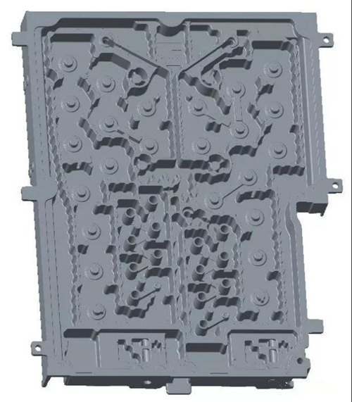
Figure 1 The structure of the filter
Casting the product is difficult based on the above analysis. Studying the filling of the runner system and exhaust of the overflow system of this product is the first factor to be considered to solve the gas hole.
The description for the defect
According to the results of die-cast trial production, some irregular gas holes were found on the peripheral surface of a pedestal at the left end of the casting. The largest diameter for the gas hole is 3 mm, and the smallest 0.5 mm. The gas holes are mostly round and elliptical. Some of them have shapes like strips, and the inside of the hole is smooth (see Figure 2). After X-ray inspection, it was found that the air holes at this location were clustered and distributed around the pedestal. The internal quality of the X-ray is shown in Figure 3. Therefore, it can be preliminarily judged that the gas hole was caused by gas accumulation, and the product's rejection rate caused by the defect in production reached 27.8%.
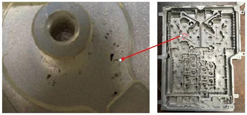
Figure 2 The picture of gas holes
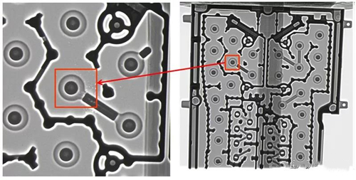
Figure 3 The picture of the gas hole by the X-ray inspection
The cause analysis of the gas hole
The analysis of the product structure
The area A on the left is the space between the inner cavity structure and wall of the water tail analyzed from the product structure (see Figure 4). When the molten aluminum is filled to this position, it meets the mold wall and forms a wrap, which affects the filling and exhaust of the molten aluminum. When the exhaust is not smooth, high pressure will occur, which will cause difficulty in melt filling and insufficient injection volume, resulting in the defects such as loose structure and exposed gas holes in the C zone of the casting. There are no defects for the transition position between the A zone and C zone, because it is relatively close to the tail and the overflow system can discharge part of the gas. The structure of the zone B on the right is connected to the wall of the water tail, which can be filled and exhausted smoothly, so there is no gas hole in the production. In addition, the die-cast engineer at the trial-production site conducts trial-production under good process conditions, and the situation of gas holes caused by the die casting process doesn't exist, such as excessive gas content in the aluminum liquid, excessive spraying, and unreasonable injection process parameters.
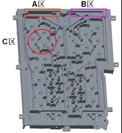
Figure 4 The structure analysis of the product
CAE simulation analysis
Use MAGMA simulation software to simulate the die-cast scheme. Figure 5 shows the different filling volumes: 40%, 60%, 80% and 100%, it is found that the filling of the left half of the product is slower than that of the right half; and the filling speed of the gate 1 is slower than that of the gate 2. An entrained gas area appears in the upper left corner of the product.
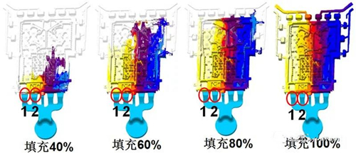
Figure 5 The CAE analysis of the filling of the product
The improvement on the defect
Solutions to defects
From the MAGMA simulation, the filling speed of gate 1 is too fast, and that of the gate 2 is too slow, causing the leftmost aluminum to quickly seal the slag bag at the tail, resulting in poor exhaust and forming an air entrainment area. In addition, the filling of the left half of the product is slower than that of the right half. The improvement plan we proposed was to reduce the filling speed of gate 1 by half sealing, and to increase the width of the gate 2 by 5 mm to the left to speed up the filling speed, so that the filling of the left and right sides of the product tended to be balanced. In addition, in order to improve the exhaust, the exhaust channel was provided for the slag bags 3 and 4, so that the gas on the left and right corners of the product was directly discharged to the exhaust plate of the mold (See Figure 6).
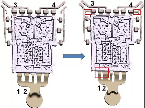
Figure 6 The improved scheme
The CAE analysis for the improved plan
We put the improved plan in the MAGMA software for CAE simulation. After the runner was modified, the filling speed of the left half of the product was faster than before, and the left half and right half of the filling tended to be balanced; the filling of the gate 1 was slower than that of the gate 2, and no air entrainment area was formed in the upper left corner of the product. See Figure 7.
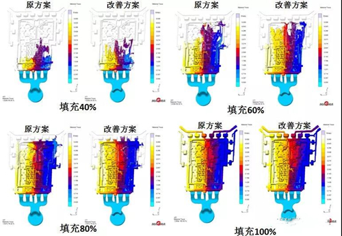
Figure 7 A comparison of CAE analysis of the original plan and the improved plan
The verification of the improved effect
After on-site trial production, the internal quality of the X-ray was shown in Figure 8. There were no gas holes in the defect position. The rejection rate at this location caused by gas holes has changed from 27.8% to 0%. The quality of the product met the technical requirements, and the project successfully passed verification and was mass-produced through mass production, sampling, and testing by users.
This case is an example of the combination of on-site die casting process and CAE technology to solve the problem of gas holes, shortening the development cycle of new products, and greatly improving economic benefits.
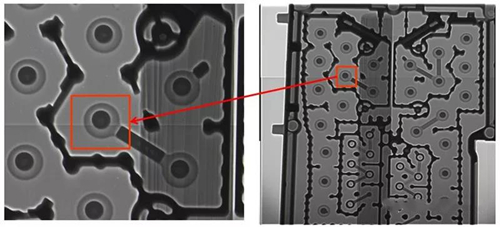
Figure 8 X-ray image of trial production after mold modification
Take a filter for communication components as an example. Use CAE to simulate the original plan and analyze the root cause of the defect; propose an optimized plan to effectively solve the problem of gas holes of the product.
Figure 1 is a structural picture of a certain filter for a communication component. The weight of the casting is 3 kg, and the material is DC01. The size of the casting is 414×333×38 mm. The maximum wall thickness is 4 mm. The minimum wall thickness is 2 mm, and the average wall thickness is 3 mm. The inner cavity is staggered with ribs similar to the labyrinth structure, which is a relatively complex casting. This part is a filter used in mobile communication transmitter base stations with high technology so far. Compared with the traditional filter, its internal cavity structure is more complicated, and there are many and complicated labyrinth structures. The wall thickness is uneven, and there are many columns and mounting holes. The complicated structure will inevitably lead to insufficient filling of the molten aluminum and the occurrence of partial wrapping gas in the casting. In addition, the requirement for internal compactness of the casting is high, and the product needs to be electroplated. When the casting is electroplated and baked, the gas in the hole is heated and expands, which will cause bubbles on the surface of the casting. Therefore, appropriate methods must be used to solve the gas hole in the production. How to reduce the gas in the casting is a difficulty in the design of the entire die-cast process.
Figure 1 The structure of the filter
Casting the product is difficult based on the above analysis. Studying the filling of the runner system and exhaust of the overflow system of this product is the first factor to be considered to solve the gas hole.
The description for the defect
According to the results of die-cast trial production, some irregular gas holes were found on the peripheral surface of a pedestal at the left end of the casting. The largest diameter for the gas hole is 3 mm, and the smallest 0.5 mm. The gas holes are mostly round and elliptical. Some of them have shapes like strips, and the inside of the hole is smooth (see Figure 2). After X-ray inspection, it was found that the air holes at this location were clustered and distributed around the pedestal. The internal quality of the X-ray is shown in Figure 3. Therefore, it can be preliminarily judged that the gas hole was caused by gas accumulation, and the product's rejection rate caused by the defect in production reached 27.8%.
Figure 2 The picture of gas holes
Figure 3 The picture of the gas hole by the X-ray inspection
The cause analysis of the gas hole
The analysis of the product structure
The area A on the left is the space between the inner cavity structure and wall of the water tail analyzed from the product structure (see Figure 4). When the molten aluminum is filled to this position, it meets the mold wall and forms a wrap, which affects the filling and exhaust of the molten aluminum. When the exhaust is not smooth, high pressure will occur, which will cause difficulty in melt filling and insufficient injection volume, resulting in the defects such as loose structure and exposed gas holes in the C zone of the casting. There are no defects for the transition position between the A zone and C zone, because it is relatively close to the tail and the overflow system can discharge part of the gas. The structure of the zone B on the right is connected to the wall of the water tail, which can be filled and exhausted smoothly, so there is no gas hole in the production. In addition, the die-cast engineer at the trial-production site conducts trial-production under good process conditions, and the situation of gas holes caused by the die casting process doesn't exist, such as excessive gas content in the aluminum liquid, excessive spraying, and unreasonable injection process parameters.
Figure 4 The structure analysis of the product
CAE simulation analysis
Use MAGMA simulation software to simulate the die-cast scheme. Figure 5 shows the different filling volumes: 40%, 60%, 80% and 100%, it is found that the filling of the left half of the product is slower than that of the right half; and the filling speed of the gate 1 is slower than that of the gate 2. An entrained gas area appears in the upper left corner of the product.
Figure 5 The CAE analysis of the filling of the product
The improvement on the defect
Solutions to defects
From the MAGMA simulation, the filling speed of gate 1 is too fast, and that of the gate 2 is too slow, causing the leftmost aluminum to quickly seal the slag bag at the tail, resulting in poor exhaust and forming an air entrainment area. In addition, the filling of the left half of the product is slower than that of the right half. The improvement plan we proposed was to reduce the filling speed of gate 1 by half sealing, and to increase the width of the gate 2 by 5 mm to the left to speed up the filling speed, so that the filling of the left and right sides of the product tended to be balanced. In addition, in order to improve the exhaust, the exhaust channel was provided for the slag bags 3 and 4, so that the gas on the left and right corners of the product was directly discharged to the exhaust plate of the mold (See Figure 6).
Figure 6 The improved scheme
The CAE analysis for the improved plan
We put the improved plan in the MAGMA software for CAE simulation. After the runner was modified, the filling speed of the left half of the product was faster than before, and the left half and right half of the filling tended to be balanced; the filling of the gate 1 was slower than that of the gate 2, and no air entrainment area was formed in the upper left corner of the product. See Figure 7.
Figure 7 A comparison of CAE analysis of the original plan and the improved plan
The verification of the improved effect
After on-site trial production, the internal quality of the X-ray was shown in Figure 8. There were no gas holes in the defect position. The rejection rate at this location caused by gas holes has changed from 27.8% to 0%. The quality of the product met the technical requirements, and the project successfully passed verification and was mass-produced through mass production, sampling, and testing by users.
This case is an example of the combination of on-site die casting process and CAE technology to solve the problem of gas holes, shortening the development cycle of new products, and greatly improving economic benefits.
Figure 8 X-ray image of trial production after mold modification
Related News
- Industrialization of the Composite 3D Printing for General Motors
- Porsche and GM Have Obtained Achievement in 3D Printing Auto Parts Technology
- Development of Aluminum Alloy Die Castings for Automobile Steering Knuckles (Part Two)
- Development of Aluminum Alloy Die Castings for Automobile Steering Knuckles (Part One)
- Die Casting Technologies of Automobile Structural Parts (Part Three)
- The Die Casting Technology of Automobile Structural Parts (Part Two)
- The Die Casting Technology of Automobile Structural Parts (Part One)
- Application of Heat-Free Aluminum Alloys to Integrated Die-Casting
- Mechanical Properties and Microstructure of Heat-Free Alloys
- Designing Die-Cast Molds for Complex Shells
News
Contact
Latest News

Technical Articles

Useful Links
Copyright © 2014-2026 China Topper Die Casting Company Limited. All Rights Reserved. Privacy Policy | Terms of Service | Sitemap
Links: Die Casting, Linear Robot Arm for Die Casting Machine, China Manufacturers.
Website Design & Support: jeawin.com