Analyzing the Defects in the Die Casting Simulation Results
Simulation technology is also known as the mold flow analysis that has been generally accepted and applied with the development of the die casting industry in the past two years, and its practical role has become increasingly prominent in the using process, which can help companies optimize design, improve technology, and save costs. However, in the process of using mold flow software, analyzing the simulation results is a pain in the ass for engineers. This article will start with two common surface defects and describe the train of thought for the interpretation of simulation results.
1. Wrinkles on the surface
The first defect is the wrinkle on the surface which is common to be seemed. Before using simulation software to analyze, it is necessary to clarify the characteristics and causes of this defect. The wrinkle on the surface mainly refers to irregular wrinkles on the surface of the die-cast part. Check figure 1 for more information.
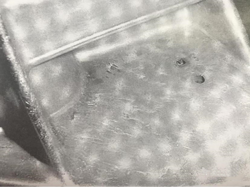
Figure 1 The wrinkle on the surface
There are two main reasons for this defect: One is that the mold and molten metal temperatures are low and the molten metal forms a solidified layer with an oxide film due to the low temperature in the flow process, and the other is that the air in the cavity is not fully discharged. After understanding the cause of the defect, it can be analyzed based on the cause and simulation result. Figure 2 shows a fan shell. In actual production, there are surface wrinkles in the area inside the red square.
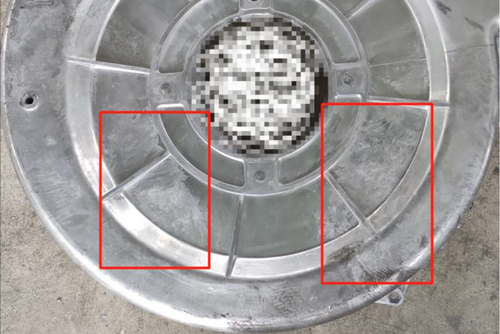
Figure 2 Wrinkles on the surface of the fan housing
The following is a simulation analysis of this product with the help of die-cast simulation cloud platform. Figure 3 shows the simulated filling temperature results. The blue area indicated by the arrow indicates the low-temperature area in the filling process, and the defected area is relatively close to the simulated low-temperature area. Corresponds to the first reason for the formation of defects. Therefore, the defects on the fan housing may be surface wrinkles caused by the low temperature.
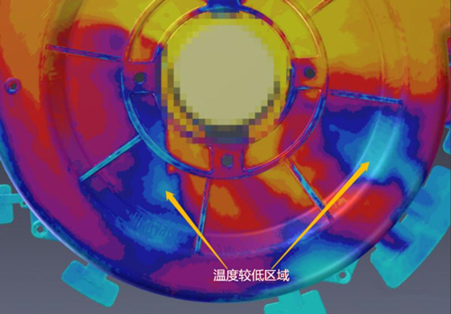
Figure 3 Filling temperature results
Figure 4 is the result of the simulated filling time. The area indicated by the arrow represents a longer filling time, in other words, the filling lags behind. It can be seen that the filling time of the defective area is relatively longer, and that of the surrounding area is relatively shorter. There is a situation in which the surrounding area is filled first, and the inner area is filled later, that is, there is a partial situation where the air in the cavity is drawn into. It corresponds to the second reason.
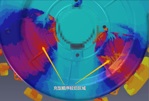
Figure 4 Filling time results
2. Flow marks or patterns
The second defect is the flow mark, which is also called the pattern. It is also necessary to first understand the characteristics and causes of flow marks. The main characteristic of flow marks is the formation of irregular stripes on the surface of the die casting part, which is consistent with the flow direction of the molten metal. Speaking of the formation of flow marks, different adhesion states of the mold release agent on the surface of the cavity due to the turbulent flow of molten metal in the cavity and differences in the oxidation state of the surface of the die casting part make flow marks or patterns eventually appear on the surface of the die casting part. Figure 5 shows the common appearance of flow marks on castings.
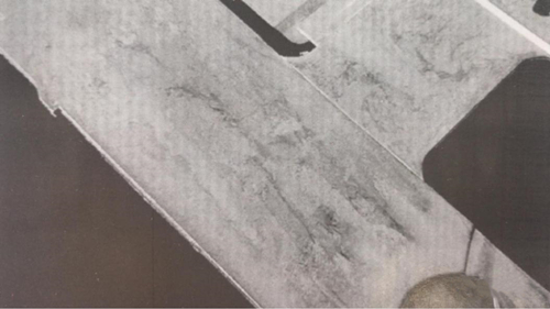
Figure 5 The appearance of flow marks
Figure 6 shows the flow marks or patterns that appear on the fan housing, mainly concentrated in the area within the red square.
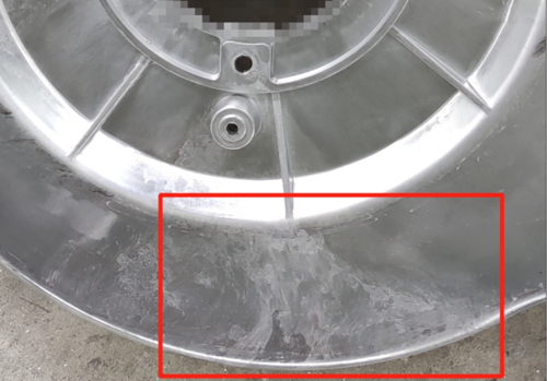
Figure 6 Flow marks or patterns on the surface of the fan housing
Let's take a look at the simulation results. Figure 7 is the result of the simulated liquid flow tracking. It can be seen that the surface defects here are caused by the molten metal fed on the left side, and are not related to the molten metal fed on the right side. According to the analysis in Figure 8 (temperature results), the temperature in this area is relatively low, and there is a big difference from other surrounding temperatures. This causes the surface condition of this area to be different from other areas, and flow marks (patterns) finally form on the surface of the product.
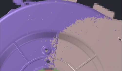
Figure 7 Tracking results of liquid flows
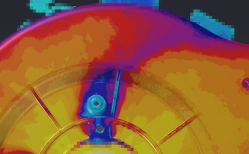
Figure 8 Filling temperature results
Finding the real cause of the surface wrinkles and flow marks (patterns) of the fan shell through the simulation can provide certain directional suggestions for optimizing the mold design or die-cast process parameters, making the accurate adjustment, reducing the number of testing and error, and playing a role in reducing costs.
1. Wrinkles on the surface
The first defect is the wrinkle on the surface which is common to be seemed. Before using simulation software to analyze, it is necessary to clarify the characteristics and causes of this defect. The wrinkle on the surface mainly refers to irregular wrinkles on the surface of the die-cast part. Check figure 1 for more information.
Figure 1 The wrinkle on the surface
There are two main reasons for this defect: One is that the mold and molten metal temperatures are low and the molten metal forms a solidified layer with an oxide film due to the low temperature in the flow process, and the other is that the air in the cavity is not fully discharged. After understanding the cause of the defect, it can be analyzed based on the cause and simulation result. Figure 2 shows a fan shell. In actual production, there are surface wrinkles in the area inside the red square.
Figure 2 Wrinkles on the surface of the fan housing
The following is a simulation analysis of this product with the help of die-cast simulation cloud platform. Figure 3 shows the simulated filling temperature results. The blue area indicated by the arrow indicates the low-temperature area in the filling process, and the defected area is relatively close to the simulated low-temperature area. Corresponds to the first reason for the formation of defects. Therefore, the defects on the fan housing may be surface wrinkles caused by the low temperature.
Figure 3 Filling temperature results
Figure 4 is the result of the simulated filling time. The area indicated by the arrow represents a longer filling time, in other words, the filling lags behind. It can be seen that the filling time of the defective area is relatively longer, and that of the surrounding area is relatively shorter. There is a situation in which the surrounding area is filled first, and the inner area is filled later, that is, there is a partial situation where the air in the cavity is drawn into. It corresponds to the second reason.
Figure 4 Filling time results
2. Flow marks or patterns
The second defect is the flow mark, which is also called the pattern. It is also necessary to first understand the characteristics and causes of flow marks. The main characteristic of flow marks is the formation of irregular stripes on the surface of the die casting part, which is consistent with the flow direction of the molten metal. Speaking of the formation of flow marks, different adhesion states of the mold release agent on the surface of the cavity due to the turbulent flow of molten metal in the cavity and differences in the oxidation state of the surface of the die casting part make flow marks or patterns eventually appear on the surface of the die casting part. Figure 5 shows the common appearance of flow marks on castings.
Figure 5 The appearance of flow marks
Figure 6 shows the flow marks or patterns that appear on the fan housing, mainly concentrated in the area within the red square.
Figure 6 Flow marks or patterns on the surface of the fan housing
Let's take a look at the simulation results. Figure 7 is the result of the simulated liquid flow tracking. It can be seen that the surface defects here are caused by the molten metal fed on the left side, and are not related to the molten metal fed on the right side. According to the analysis in Figure 8 (temperature results), the temperature in this area is relatively low, and there is a big difference from other surrounding temperatures. This causes the surface condition of this area to be different from other areas, and flow marks (patterns) finally form on the surface of the product.
Figure 7 Tracking results of liquid flows
Figure 8 Filling temperature results
Finding the real cause of the surface wrinkles and flow marks (patterns) of the fan shell through the simulation can provide certain directional suggestions for optimizing the mold design or die-cast process parameters, making the accurate adjustment, reducing the number of testing and error, and playing a role in reducing costs.
Related News
- Industrialization of the Composite 3D Printing for General Motors
- Porsche and GM Have Obtained Achievement in 3D Printing Auto Parts Technology
- Development of Aluminum Alloy Die Castings for Automobile Steering Knuckles (Part Two)
- Development of Aluminum Alloy Die Castings for Automobile Steering Knuckles (Part One)
- Die Casting Technologies of Automobile Structural Parts (Part Three)
- The Die Casting Technology of Automobile Structural Parts (Part Two)
- The Die Casting Technology of Automobile Structural Parts (Part One)
- Application of Heat-Free Aluminum Alloys to Integrated Die-Casting
- Mechanical Properties and Microstructure of Heat-Free Alloys
- Designing Die-Cast Molds for Complex Shells
News
Contact
Latest News

Technical Articles

Useful Links
Copyright © 2014-2026 China Topper Die Casting Company Limited. All Rights Reserved. Privacy Policy | Terms of Service | Sitemap
Links: Die Casting, Linear Robot Arm for Die Casting Machine, China Manufacturers.
Website Design & Support: jeawin.com