Die-cast Mold Design for New Energy Vehicle Motor Housings (Part one)
Abstract: The mold cooling system combined with a 3D printing water channel and high-pressure cooling is used to realize the uniform cooling of the electric vehicle motor housing mold, and the sensor and solenoid valve are connected to the control system of the die-cast equipment to realize the intelligent control of the working temperature of the mold and solve the problem of mold sticking to aluminum, improve the internal quality and production efficiency of castings. The research results have reference significance and application value for the development of auto parts with similar complex structures.
1. Drive motor shell castings
The driving motor shell is shown in Figure 1, and consists of four functional areas: the first is to install the inner shell of the motor, the stator and the rotor area; the second is the area where the output shaft assembly is installed; the third is the area where the internal circulating water cooling pipe is installed; the fourth is the installation and fixed area of the motor.
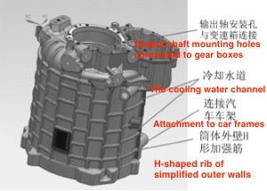
Figure 1 The shell model of the motor
To reduce the weight of the motor and improve the cruising range of electric vehicles, the casting structure design adopts finite element analysis, and the wall thickness of the motor casing is reduced to 4 mm, and the "H" shaped rib is added; The wall thickness of the output shaft assembly installation area is reduced from 15 mm to 6 mm; special-shaped ribs are provided, and the weight of the motor casing casting is reduced from the original 15kg to 8kg. The optimal design of the casting structure brings great difficulty to the design of the die-cast mold cooling system and die-cast process parameters. The die-cast mold cooling, temperature intelligent control system, die-cast process parameters, quality and production efficiency of shell castings.
2. Die-cast mold design
2.1 Cooling systems
Figure 2 is a picture of the motor housing. The porosity rate is not more than 4%. The cylinder part of the motor housing is relatively large, with a length of 500 mm and a wall thickness of 4 mm. Filling the cavity with aluminum liquid for a long distance will inevitably lead to a sharp increase in mold temperature. The wall thickness of the G area with the complex structure in the inner cavity of the shell is the thickest and the temperature is the highest from the mold flow simulation temperature field shown in Figure 3, which will inevitably cause aluminum sticking, internal porosity, air holes or shrinkage cavities, high-pressure point cooling straight water channel not to be processed. Designing this part as an insert and using a 3D printing cooling water channel to directly connect with the high-pressure cooling water pipe of the mold core can solve the cooling of the G area. As shown in Figure 4, 1 is the part of the mold insert part that realizes the cooling water channel. To ensure the distance between the cooling water channel and the outer surface of the mold cavity, only a 3D printing water channel with a diameter of 1 mm can be used at the sharp corner of the special-shaped structure in Figure 1. Ensure that the outer wall of the water channel in the high-temperature zone G in Figure 3 is less than 8 mm from the mold surface, achieving precise conformal cooling, ensuring that the distance from the cooling water channel to the outer surface of the mold cavity is equal, and solving the problem of unbalanced thermal conductivity of the complex mold surface. 2 is a high-pressure inlet and outlet channel; one end is connected to the high-pressure cooling device, and the other end is connected to the return water pipe of the workshop.
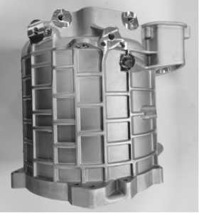
Figure 2 The motor housing
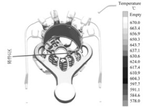
Figure 3 The temperature field
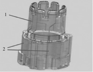
Figure 4 3D printing inserts
2.2 The selection of alloy powder
Select alloy powders with good purity, good fluidity and good sphericity which are mainly composed of iron, manganese, nickel, chromium, molybdenum, tungsten, etc., and use laser fusion deposition method to make 3D conformal cooling channel inserts. After isostatic pressing, vacuum quenching, solution annealing, precision machining, and surface laser coating treatment, the mechanical properties of the 3D printed insert body are shown in Table 1.
Table 1 Mechanical properties of materials
1. Drive motor shell castings
The driving motor shell is shown in Figure 1, and consists of four functional areas: the first is to install the inner shell of the motor, the stator and the rotor area; the second is the area where the output shaft assembly is installed; the third is the area where the internal circulating water cooling pipe is installed; the fourth is the installation and fixed area of the motor.
Figure 1 The shell model of the motor
To reduce the weight of the motor and improve the cruising range of electric vehicles, the casting structure design adopts finite element analysis, and the wall thickness of the motor casing is reduced to 4 mm, and the "H" shaped rib is added; The wall thickness of the output shaft assembly installation area is reduced from 15 mm to 6 mm; special-shaped ribs are provided, and the weight of the motor casing casting is reduced from the original 15kg to 8kg. The optimal design of the casting structure brings great difficulty to the design of the die-cast mold cooling system and die-cast process parameters. The die-cast mold cooling, temperature intelligent control system, die-cast process parameters, quality and production efficiency of shell castings.
2. Die-cast mold design
2.1 Cooling systems
Figure 2 is a picture of the motor housing. The porosity rate is not more than 4%. The cylinder part of the motor housing is relatively large, with a length of 500 mm and a wall thickness of 4 mm. Filling the cavity with aluminum liquid for a long distance will inevitably lead to a sharp increase in mold temperature. The wall thickness of the G area with the complex structure in the inner cavity of the shell is the thickest and the temperature is the highest from the mold flow simulation temperature field shown in Figure 3, which will inevitably cause aluminum sticking, internal porosity, air holes or shrinkage cavities, high-pressure point cooling straight water channel not to be processed. Designing this part as an insert and using a 3D printing cooling water channel to directly connect with the high-pressure cooling water pipe of the mold core can solve the cooling of the G area. As shown in Figure 4, 1 is the part of the mold insert part that realizes the cooling water channel. To ensure the distance between the cooling water channel and the outer surface of the mold cavity, only a 3D printing water channel with a diameter of 1 mm can be used at the sharp corner of the special-shaped structure in Figure 1. Ensure that the outer wall of the water channel in the high-temperature zone G in Figure 3 is less than 8 mm from the mold surface, achieving precise conformal cooling, ensuring that the distance from the cooling water channel to the outer surface of the mold cavity is equal, and solving the problem of unbalanced thermal conductivity of the complex mold surface. 2 is a high-pressure inlet and outlet channel; one end is connected to the high-pressure cooling device, and the other end is connected to the return water pipe of the workshop.
Figure 2 The motor housing
Figure 3 The temperature field
Figure 4 3D printing inserts
2.2 The selection of alloy powder
Select alloy powders with good purity, good fluidity and good sphericity which are mainly composed of iron, manganese, nickel, chromium, molybdenum, tungsten, etc., and use laser fusion deposition method to make 3D conformal cooling channel inserts. After isostatic pressing, vacuum quenching, solution annealing, precision machining, and surface laser coating treatment, the mechanical properties of the 3D printed insert body are shown in Table 1.
Table 1 Mechanical properties of materials
| 3D printing insert body sampling | Yield limit Rp0.2/MPa |
Tensile strength R/MPa | Elongation 4% |
Porosity/% |
Surface hardness Hv |
| Iron, manganese, aluminum, molybdenum and tungsten alloys | 1300 |
1500 |
6 | 0.05 |
2500 |
2.3 Intelligent control of cooling water
From the analysis of the temperature field data in Figure 3, it can be concluded that the temperature in the G area of the casting is the highest and has the greatest impact on the quality of the casting. As long as the temperature in the G area is controlled, the internal quality of the entire casting will be solved. Installing the thermocouple on the opposite side of the G area of the 3D printing insert has the best effect of detecting the temperature of the mold. As shown in Figure 5, the thermocouple converts the thermoelectric potential information generated by the temperature into a temperature digital signal within 3 ms, and is connected to the die-cast machine through the thermocouple plug shown in Figure 6. The die-cast machine stores the received temperature signal in the reservoir and compares it with the set value of the mold temperature. When the mold temperature exceeds the set upper limit of 205°C, as shown in Figure 7, all three groups of parallel cooling water control solenoid valves are opened. The mold cooling water flow rate increases as shown in Figure 8, and the mold temperature drops rapidly; when the mold temperature is lower than the set lower line of 190°C, the three sets of parallel solenoid valves are closed in turn until the mold temperature rises to the set range. The rest of the solenoid valves are no longer closed, and the dynamic balance of the mold temperature is realized, as shown in Figure 9.
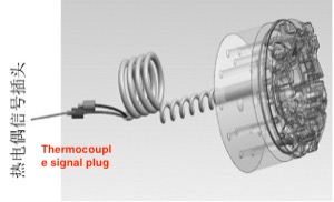
Figure 5 Monitoring the mold temperature
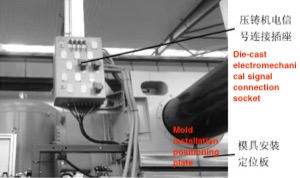
Figure 6 Die casting machines
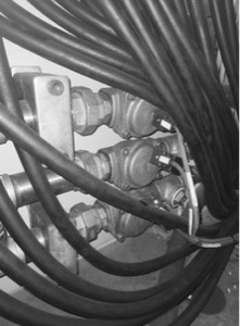
Figure 7 Solenoid valves
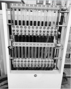
Figure 8 Mold cooling devices
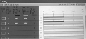
Figure 9 The interface of the mold temperature monitoring system

Related News
- Impact of Heat Treatment on Mechanical Properties and Thermal Conductivity of ZL102 Alloy
- Impact of T6 Heat Treatment on ADC12 Aluminum Alloy Properties
- Enhancing the Mechanical Properties of ADC12 Aluminum Alloy via T6 Heat Treatment
- Die-Casting Process Design of Valve Bodies for Automobile Oil Cylinder Parts
- Temperature Field Simulation & Optimization of Automotive Housing Die Castings
- Research Status of High-Impact Aluminum Alloys Domestically and Internationally
- Die-cast Aluminum Castings for High-speed Rail Rocker Arm Shells
- Aluminum Alloys for Automobile Body Panels
- Analysis and Measures of Internal Shrinkage Cavities in Aluminum Die Castings
- Advantages of Aluminum Alloys in Lightweight Automobiles
News
Contact
Latest News

Technical Articles

Useful Links
Copyright © 2014-2026 China Topper Die Casting Company Limited. All Rights Reserved. Privacy Policy | Terms of Service | Sitemap
Links: Die Casting, Linear Robot Arm for Die Casting Machine, China Manufacturers.
Website Design & Support: jeawin.com