Design of Die-cast Molds for Large and Complicated Gearbox Shells
In recent years, the demand for large die-cast molds has increased due to the continuous development of the domestic automobile industry. Since the quality of such products will directly affect the performance of automobile engines and gearboxes, and the subsequent processing and manufacturing costs are high, the requirements for the yield, production efficiency, manufacturing cost and reliability of such molds are higher. The multi-slider nested core-pulling mechanism and mold's cooling system are introduced based on the structural characteristics of the shape and hole position of a certain automobile gearbox housing, starting from the design of the gating system of the die casting part. Finally, a qualified product is obtained.
1. The structural analysis of a gearbox housing
Figure 1 shows the die casting part of a certain automobile gearbox housing made from ADC12 aluminum alloys, with an outline size of 550 mm × 444 mm × 301 mm, and a total mass of about 27.3 kg, which is a large-scale die-cast part. The product has a complex structure, many ribs and holes. The main wall thickness is 7 mm and the wall thickness is uneven. It can be seen from Figure 1 that there are many holes on the outer side of the product, and the slider structure needs to be designed for 4 directions of the mold. It can be seen from Figure 1a that the product has a lot of holes and thicker walls in partial areas, and high requirements for air tightness of the bearing holes and cylinder holes are put forward. From Figure 1b, it can be seen that there is a deep cavity structure inside the product; the big center part of the bearing hole of the two sides cannot be made by the die casting process. It needs to be completely filled and connected to the bottom. Later, it needs to be processed by machining. After the part is connected, there is a greater risk of internal defects due to problems of the deep cavity and wall thickness. This is difficulty 1. In addition, there are many and dense side holes. When the cooling system of the mold is arranged, it is difficult and complicated. At the same time, there are 8 threaded holes that are different from the direction. There is a great angle between the two. Core-pulling from the same direction can't be realized. It is necessary to design the core-pulling mechanism separately to ensure internal quality. This is difficulty 2. See Figures 1b and 1c.
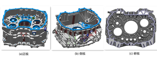
Figure 1 Three-dimensional models of gearbox housings
2. Design of the gating system
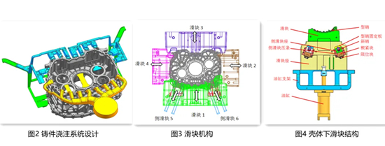
The product's structure and gating system play a decisive role in the mold structure. A reasonable gating system can not only ensure the quality of the die castings, but also simplify the mold. In order to solve the difficulty 1 and ensure the internal quality of the large bearing holes on both sides, make small improvements to the product (Figure 2); add some dense small grids on the surface of the bearing holes to alleviate the surface defects of the die casting part, especially the holes, and increase the surface area, thereby increasing the heat dissipation surface and improving the heat dissipation efficiency.
The gating and exhausting system is designed on the end faces (machined surfaces) of the large bearing holes on both sides (see Figure 2), and a branch is specially designed to fill the large bearing holes at a distance to ensure the internal quality of the bearing holes; Create a slag collecting bag at the remote or gathering part of the die casting to ensures that the remote cold material, gas, and slag can flow to it with a maximum amount to eliminate die casting defects. In addition, this gating system can be removed using a mechanical electric saw or subsequent trimming die, and the remaining pouring risers can be removed by machining; the appearance of the die castings is of good quality.
After adopting this gating system, the mold parting surface can only be selected near the end faces of the large bearing holes on both sides. The shallow cavity in the front is designed on the fixed mold, and the deep cavity at the back is designed on the movable mold. Four sliders are designed on the left, right, up and down sides. The complicated side in Figure 1b is located at the bottom of the mold.
3. The design of the mold
3.1 The structural design of the slider
According to the structural characteristics of the die casting, in addition to the movable and fixed molds, the mold splitting is provided at the reinforcing ribs around the die casting (Figure 3). Because the angle of the 8 threaded holes is inconsistent with the bottom ejection direction angle (The mold is designed as a pin.), two side sliders 5 and 6 are designed. Use a nested core pulling mechanism with multiple sliders, which is also called a two-stage linkage core pulling mechanism. Use their respective transmission elements. When the mold is opened, the side sliders 5 and 6 are first drawn, and then the slide block 1 to complete the opening of the mold. When the mold is closed, the large slide block 1 is reset, and then the small slide block.
3.2 The design of secondary core pulling structure
Figure 4 shows the lower sliding block structure of the housing, and Figure 5 shows the secondary core pulling action process. After the die casting part is formed and the mold is opened, the mold opening force makes the inclined pin and inclined hole of the side sliders 5 and 6 have a relative movement. Since the side slider is installed in the layering groove of the movable template in the form of a clearance fit, the side slider is driven to move outward. After moving to the core-pulling distance, the side core-pulling and mold opening actions are completed. At this time, under the action of the limited block, the side slider accurately stays at the end position when the slider is pulled for the oblique pin, so as to prevent the oblique pin and oblique hole from being misaligned during the next mold clamping, and a collision accident may occur.
When the mold is clamped, the inclined pin accurately enters the inclined hole of the side slider and brings the reset action. However, it is difficult to only rely on the positioning of the diagonal pin, and the pressure maintaining of the diagonal pin will cause the side slider to retreat when it is impacted by the high pressure of the injection pressure. Therefore, the locking device of the side slide block is designed, namely the wedge block, and its inner side is in contact with the tail of the small slide block with an inclined surface to ensure the precise positioning of the side core and lock the side slide block to prevent displacement or retreat due to side injection pressure.

Figure 5 The process of the secondary core pulling
3.3 The design of the mold's cooling system
The mold's cooling system plays a key factor in the quality of the die casting, service life of the mod and production stability. In order to ensure the internal quality of this die casting part, various types of waterways are designed around the mold and at the upper and lower positions, as shown in Figure 6. It can be seen from Figure 6a that large circulating cooling is designed on the movable and fixed molds, and point cooling or high-pressure cooling is designed for parts with deep cavities to eliminate the problems of shrinkage cavity, cracks and mold sticking caused by partial overheating as much as possible. The nested core-pulling mechanism design leads to small space when the large circulating cooling water is arranged. Only one set of circulating cooling is designed on the periphery, and multiple point cooling at the overheating position is designed. The multi-layer circulating cooling is mainly adopted for the remaining two sides due to the deep cavity position and fewer holes, ensuring the stability and balance of the mold temperature. It can be seen from Figure 6b that a complex set of cyclic cooling is designed on the two secondary core pullings, which can not only cool each pin, but also cool the inclined core pulling mechanism, so that the core pulling mechanism works smoothly and have low malfunctions and high production efficiency.

Figure 6 The design of the cooling system
4. Verification by production
The mold was made using the above-mentioned design scheme, and production was carried out. Figure 7 is a photo of qualified products of die casting parts. After machining the bearing holes on both sides and the 8 threaded holes at the bottom of the product, there were no obvious defects. Through actual production verification, molds with this structure can solve the problem of different core-pulling directions on the same side; the core-pulling is stable and ejection is safe. The quality and size of the die casting part can meet the requirements for the product, and mass production has been realized.

Figure 7 Qualified products
1. The structural analysis of a gearbox housing
Figure 1 shows the die casting part of a certain automobile gearbox housing made from ADC12 aluminum alloys, with an outline size of 550 mm × 444 mm × 301 mm, and a total mass of about 27.3 kg, which is a large-scale die-cast part. The product has a complex structure, many ribs and holes. The main wall thickness is 7 mm and the wall thickness is uneven. It can be seen from Figure 1 that there are many holes on the outer side of the product, and the slider structure needs to be designed for 4 directions of the mold. It can be seen from Figure 1a that the product has a lot of holes and thicker walls in partial areas, and high requirements for air tightness of the bearing holes and cylinder holes are put forward. From Figure 1b, it can be seen that there is a deep cavity structure inside the product; the big center part of the bearing hole of the two sides cannot be made by the die casting process. It needs to be completely filled and connected to the bottom. Later, it needs to be processed by machining. After the part is connected, there is a greater risk of internal defects due to problems of the deep cavity and wall thickness. This is difficulty 1. In addition, there are many and dense side holes. When the cooling system of the mold is arranged, it is difficult and complicated. At the same time, there are 8 threaded holes that are different from the direction. There is a great angle between the two. Core-pulling from the same direction can't be realized. It is necessary to design the core-pulling mechanism separately to ensure internal quality. This is difficulty 2. See Figures 1b and 1c.
Figure 1 Three-dimensional models of gearbox housings
2. Design of the gating system
The product's structure and gating system play a decisive role in the mold structure. A reasonable gating system can not only ensure the quality of the die castings, but also simplify the mold. In order to solve the difficulty 1 and ensure the internal quality of the large bearing holes on both sides, make small improvements to the product (Figure 2); add some dense small grids on the surface of the bearing holes to alleviate the surface defects of the die casting part, especially the holes, and increase the surface area, thereby increasing the heat dissipation surface and improving the heat dissipation efficiency.
The gating and exhausting system is designed on the end faces (machined surfaces) of the large bearing holes on both sides (see Figure 2), and a branch is specially designed to fill the large bearing holes at a distance to ensure the internal quality of the bearing holes; Create a slag collecting bag at the remote or gathering part of the die casting to ensures that the remote cold material, gas, and slag can flow to it with a maximum amount to eliminate die casting defects. In addition, this gating system can be removed using a mechanical electric saw or subsequent trimming die, and the remaining pouring risers can be removed by machining; the appearance of the die castings is of good quality.
After adopting this gating system, the mold parting surface can only be selected near the end faces of the large bearing holes on both sides. The shallow cavity in the front is designed on the fixed mold, and the deep cavity at the back is designed on the movable mold. Four sliders are designed on the left, right, up and down sides. The complicated side in Figure 1b is located at the bottom of the mold.
3. The design of the mold
3.1 The structural design of the slider
According to the structural characteristics of the die casting, in addition to the movable and fixed molds, the mold splitting is provided at the reinforcing ribs around the die casting (Figure 3). Because the angle of the 8 threaded holes is inconsistent with the bottom ejection direction angle (The mold is designed as a pin.), two side sliders 5 and 6 are designed. Use a nested core pulling mechanism with multiple sliders, which is also called a two-stage linkage core pulling mechanism. Use their respective transmission elements. When the mold is opened, the side sliders 5 and 6 are first drawn, and then the slide block 1 to complete the opening of the mold. When the mold is closed, the large slide block 1 is reset, and then the small slide block.
3.2 The design of secondary core pulling structure
Figure 4 shows the lower sliding block structure of the housing, and Figure 5 shows the secondary core pulling action process. After the die casting part is formed and the mold is opened, the mold opening force makes the inclined pin and inclined hole of the side sliders 5 and 6 have a relative movement. Since the side slider is installed in the layering groove of the movable template in the form of a clearance fit, the side slider is driven to move outward. After moving to the core-pulling distance, the side core-pulling and mold opening actions are completed. At this time, under the action of the limited block, the side slider accurately stays at the end position when the slider is pulled for the oblique pin, so as to prevent the oblique pin and oblique hole from being misaligned during the next mold clamping, and a collision accident may occur.
When the mold is clamped, the inclined pin accurately enters the inclined hole of the side slider and brings the reset action. However, it is difficult to only rely on the positioning of the diagonal pin, and the pressure maintaining of the diagonal pin will cause the side slider to retreat when it is impacted by the high pressure of the injection pressure. Therefore, the locking device of the side slide block is designed, namely the wedge block, and its inner side is in contact with the tail of the small slide block with an inclined surface to ensure the precise positioning of the side core and lock the side slide block to prevent displacement or retreat due to side injection pressure.
Figure 5 The process of the secondary core pulling
3.3 The design of the mold's cooling system
The mold's cooling system plays a key factor in the quality of the die casting, service life of the mod and production stability. In order to ensure the internal quality of this die casting part, various types of waterways are designed around the mold and at the upper and lower positions, as shown in Figure 6. It can be seen from Figure 6a that large circulating cooling is designed on the movable and fixed molds, and point cooling or high-pressure cooling is designed for parts with deep cavities to eliminate the problems of shrinkage cavity, cracks and mold sticking caused by partial overheating as much as possible. The nested core-pulling mechanism design leads to small space when the large circulating cooling water is arranged. Only one set of circulating cooling is designed on the periphery, and multiple point cooling at the overheating position is designed. The multi-layer circulating cooling is mainly adopted for the remaining two sides due to the deep cavity position and fewer holes, ensuring the stability and balance of the mold temperature. It can be seen from Figure 6b that a complex set of cyclic cooling is designed on the two secondary core pullings, which can not only cool each pin, but also cool the inclined core pulling mechanism, so that the core pulling mechanism works smoothly and have low malfunctions and high production efficiency.
Figure 6 The design of the cooling system
4. Verification by production
The mold was made using the above-mentioned design scheme, and production was carried out. Figure 7 is a photo of qualified products of die casting parts. After machining the bearing holes on both sides and the 8 threaded holes at the bottom of the product, there were no obvious defects. Through actual production verification, molds with this structure can solve the problem of different core-pulling directions on the same side; the core-pulling is stable and ejection is safe. The quality and size of the die casting part can meet the requirements for the product, and mass production has been realized.
Figure 7 Qualified products
Related News
- Industrialization of the Composite 3D Printing for General Motors
- Porsche and GM Have Obtained Achievement in 3D Printing Auto Parts Technology
- Development of Aluminum Alloy Die Castings for Automobile Steering Knuckles (Part Two)
- Development of Aluminum Alloy Die Castings for Automobile Steering Knuckles (Part One)
- Die Casting Technologies of Automobile Structural Parts (Part Three)
- The Die Casting Technology of Automobile Structural Parts (Part Two)
- The Die Casting Technology of Automobile Structural Parts (Part One)
- Application of Heat-Free Aluminum Alloys to Integrated Die-Casting
- Mechanical Properties and Microstructure of Heat-Free Alloys
- Designing Die-Cast Molds for Complex Shells
News
Contact
Latest News

Technical Articles

Useful Links
Copyright © 2014-2026 China Topper Die Casting Company Limited. All Rights Reserved. Privacy Policy | Terms of Service | Sitemap
Links: Die Casting, Linear Robot Arm for Die Casting Machine, China Manufacturers.
Website Design & Support: jeawin.com