Eliminating Heat Cracks of Aluminum Die Castings by Optimizing the Cooling Control
The cost of producing die castings is high, and in extreme cases, die castings with defects can lead to malfunctions. Shorter and shorter development cycles increase the risk of defects. Therefore, we increasingly need to use virtual casting and process development to reduce risks in advance. Although accurate prediction of shrinkage cavity has now become one of the standards of foundries in the automotive industry, the prediction of heat cracks in a certain place is still in its infancy. It is now possible to predict certain key areas, but the amount of hot cracks predicted usually exceeds the amount actually occurring. Therefore, as part of the process development, the prevention of heat cracks must still be carried out in the test stage. We are a global supplier of light metal parts. In this article, we will explain how to use simulation to quickly reduce the occurrence of heat cracks during crankcase process development. During the solidification process, stress will be generated in the die casting due to uneven cooling rate. Before reaching the solidus temperature, when the stress exceeds tensile strength of the material, the so-called heat cracks occur. See Figure 1. The great difference in the partial wall thickness of the die casting and the hindered shrinkage caused by the steel core or mold will promote the generation of heat cracks.
Figure 1: The main factors of heat cracks

The solidification of the alloy has an important influence on the formation of heat cracks. Generally speaking, when the temperature is higher than the solidus temperature, the microstructure will show brittle behavior. Even small mechanical strains caused by thermal shrinkage can cause heat cracks. If the alloy's solidification temperature range is small, the heat cracks can usually be compensated by flowing liquid metal. However, if the solidification temperature range of the alloy is big, the liquid flow will be hindered by the dense dendrite reticulation structure in the early stage, and the cracks that have been formed cannot be fed, resulting in the formation of heat cracks. The A226 alloy commonly used in crankcases has a large solidification temperature range and is well known for its tendency to heat cracks.
Detecting possible defects as early as possible
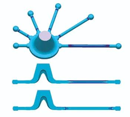
In order to analyze the critical areas of die castings, results of heat cracks at any point in the solidification and cooling stage can be calculated. When the molten metal cannot be fed through the structure of the interdendritic gap, the evaluation of the partial strain rate is an important parameter for calculating the hot crack criterion. At the same time, it is also considered that the heat crack tendency increases with the increase of solidification time. Testing die castings can be used to adjust and verify the heat crack criterion. Die-cast test rods with different length. The thick-walled areas of these test rods are prevented from shrinkage during solidification as it is shown in Figure 2. This results in the highest strain in the transition zone between thick and thin walls, and the strain increases with increase in the length of the test rod. Therefore, the shortest test rod shows the lowest heat cracks tendency, while the longest test rod shows the highest heat cracks tendency.
Figure 2: Calculation of crack sensitivity of heat crack samples

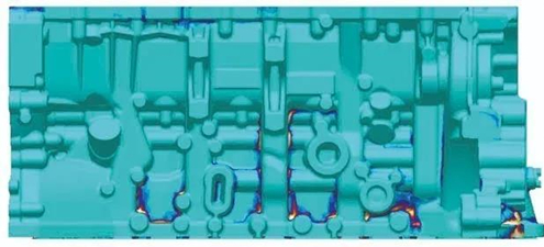
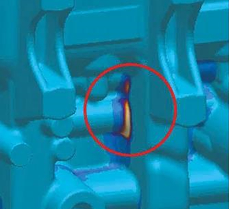
Use heat crack criteria to identify critical areas at an early stage. The stress calculation takes into account the mold's resistance to shrinkage of the die casting. Even though the current simulation calculation capability is great, this simulation calculation process is very time-consuming. Optimize the die casting process by reducing the calculation time, such as changing the cooling system of existing die castings. Qualitative risk assessment of parts prone to heat cracks can be carried out by using a very simplified model. The generality of this optimization result can be verified by using conventional hot crack prediction based on full stress calculation. In this case, the heat cracks of the crankcase repeatedly occurred in the trial production of low-pressure casting. We take this defect as the starting point for optimization and use MAGMASOFT® stress simulation to reappear the heat crack part. See Figure 3.
Figure 3: Using MAGMASOFT® to predict heat cracks of crankcases

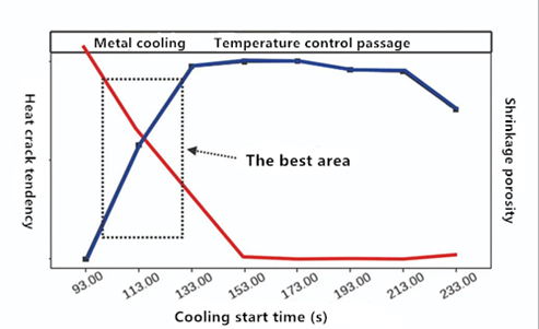
The simplified heat crack criterion is used to evaluate the difference between the solidification time of the parts where heat cracks occur and the solidification time of the part affected by the cooling system. Use MAGMASOFT®'s evaluation area function and user results to generate and evaluate criteria. The start-up time of cooling is used as a process variable, and the minimization of SHC and shrinkage is the optimization goal. The main effect diagram after optimization calculation figure 4 shows that when the cooling time is 153 seconds, the SHC is significantly reduced. After this later cooling start time, SHC did not improve significantly.
Figure 4: The effect of the cooling start time on heat cracks tendency and the risk of shrinkage cavity

On the contrary, the shrinkage cavity of selected areas will increase as the cooling time increases, which is expected. From the cooling start time of 133 seconds and longer, the shrinkage cavity did not increase significantly. Therefore, there is a typical target conflict between the two goals of optimizing heat cracks and shrinkage cavity. Obviously, the only possible time window for the optimal solution is from 93 to 133 seconds.
Validation results
In order to verify the optimization results, the start time was selected approximately in the middle of the optimal window time range, and a conventional stress simulation was performed. The shrinkage cavity of the selected area is not very serious, and the result of the heat crack criterion has been significantly lower than the original situation. In the die casting test based on the optimized cooling time, there was neither hot cracks nor shrinkage cavity in the key parts. This example clearly illustrates the effective combination of stress-based hot crack prediction and simplified models, which can effectively analyze different variables, identifying the risk parts in the die casting, and identify process variables with significant effects. In this way, quality assurance measures for die castings can be quickly worked out. See Figure 5.
Figure 5: Evaluating the impact of different cooling time on the risk of heat cracks and then verifying it in practice

Figure 1: The main factors of heat cracks

The solidification of the alloy has an important influence on the formation of heat cracks. Generally speaking, when the temperature is higher than the solidus temperature, the microstructure will show brittle behavior. Even small mechanical strains caused by thermal shrinkage can cause heat cracks. If the alloy's solidification temperature range is small, the heat cracks can usually be compensated by flowing liquid metal. However, if the solidification temperature range of the alloy is big, the liquid flow will be hindered by the dense dendrite reticulation structure in the early stage, and the cracks that have been formed cannot be fed, resulting in the formation of heat cracks. The A226 alloy commonly used in crankcases has a large solidification temperature range and is well known for its tendency to heat cracks.
Detecting possible defects as early as possible
In order to analyze the critical areas of die castings, results of heat cracks at any point in the solidification and cooling stage can be calculated. When the molten metal cannot be fed through the structure of the interdendritic gap, the evaluation of the partial strain rate is an important parameter for calculating the hot crack criterion. At the same time, it is also considered that the heat crack tendency increases with the increase of solidification time. Testing die castings can be used to adjust and verify the heat crack criterion. Die-cast test rods with different length. The thick-walled areas of these test rods are prevented from shrinkage during solidification as it is shown in Figure 2. This results in the highest strain in the transition zone between thick and thin walls, and the strain increases with increase in the length of the test rod. Therefore, the shortest test rod shows the lowest heat cracks tendency, while the longest test rod shows the highest heat cracks tendency.
Figure 2: Calculation of crack sensitivity of heat crack samples

Use heat crack criteria to identify critical areas at an early stage. The stress calculation takes into account the mold's resistance to shrinkage of the die casting. Even though the current simulation calculation capability is great, this simulation calculation process is very time-consuming. Optimize the die casting process by reducing the calculation time, such as changing the cooling system of existing die castings. Qualitative risk assessment of parts prone to heat cracks can be carried out by using a very simplified model. The generality of this optimization result can be verified by using conventional hot crack prediction based on full stress calculation. In this case, the heat cracks of the crankcase repeatedly occurred in the trial production of low-pressure casting. We take this defect as the starting point for optimization and use MAGMASOFT® stress simulation to reappear the heat crack part. See Figure 3.
Figure 3: Using MAGMASOFT® to predict heat cracks of crankcases

The simplified heat crack criterion is used to evaluate the difference between the solidification time of the parts where heat cracks occur and the solidification time of the part affected by the cooling system. Use MAGMASOFT®'s evaluation area function and user results to generate and evaluate criteria. The start-up time of cooling is used as a process variable, and the minimization of SHC and shrinkage is the optimization goal. The main effect diagram after optimization calculation figure 4 shows that when the cooling time is 153 seconds, the SHC is significantly reduced. After this later cooling start time, SHC did not improve significantly.
Figure 4: The effect of the cooling start time on heat cracks tendency and the risk of shrinkage cavity

On the contrary, the shrinkage cavity of selected areas will increase as the cooling time increases, which is expected. From the cooling start time of 133 seconds and longer, the shrinkage cavity did not increase significantly. Therefore, there is a typical target conflict between the two goals of optimizing heat cracks and shrinkage cavity. Obviously, the only possible time window for the optimal solution is from 93 to 133 seconds.
Validation results
In order to verify the optimization results, the start time was selected approximately in the middle of the optimal window time range, and a conventional stress simulation was performed. The shrinkage cavity of the selected area is not very serious, and the result of the heat crack criterion has been significantly lower than the original situation. In the die casting test based on the optimized cooling time, there was neither hot cracks nor shrinkage cavity in the key parts. This example clearly illustrates the effective combination of stress-based hot crack prediction and simplified models, which can effectively analyze different variables, identifying the risk parts in the die casting, and identify process variables with significant effects. In this way, quality assurance measures for die castings can be quickly worked out. See Figure 5.
Figure 5: Evaluating the impact of different cooling time on the risk of heat cracks and then verifying it in practice

Related News
- Industrialization of the Composite 3D Printing for General Motors
- Porsche and GM Have Obtained Achievement in 3D Printing Auto Parts Technology
- Development of Aluminum Alloy Die Castings for Automobile Steering Knuckles (Part Two)
- Development of Aluminum Alloy Die Castings for Automobile Steering Knuckles (Part One)
- Die Casting Technologies of Automobile Structural Parts (Part Three)
- The Die Casting Technology of Automobile Structural Parts (Part Two)
- The Die Casting Technology of Automobile Structural Parts (Part One)
- Application of Heat-Free Aluminum Alloys to Integrated Die-Casting
- Mechanical Properties and Microstructure of Heat-Free Alloys
- Designing Die-Cast Molds for Complex Shells


